"International friendship through amateur radio"

Month: February 2021

QCX 30m Bamotech case and calibration

QCX 30m in Bamotech custom case

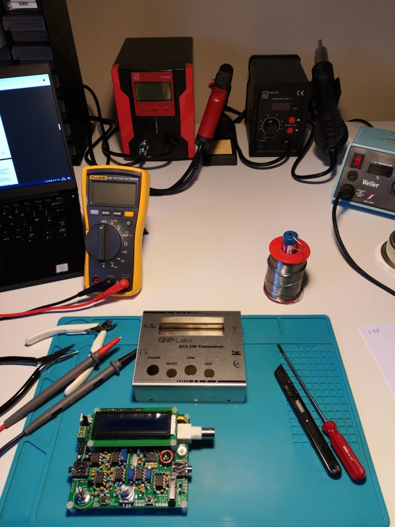
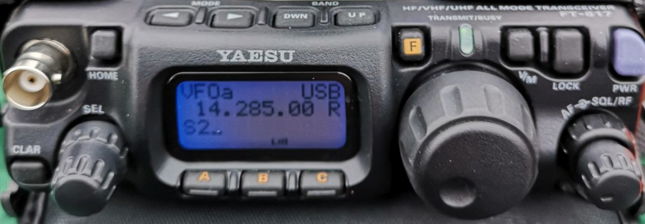
Another step nearer to using the latest addition in anger.

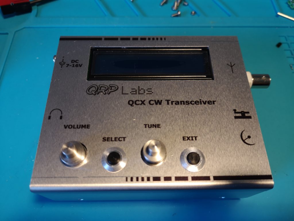
The PCB is now living in the custom built Bamotech case, is calibrated and optimised to give higher power output than the the original 0.7w.

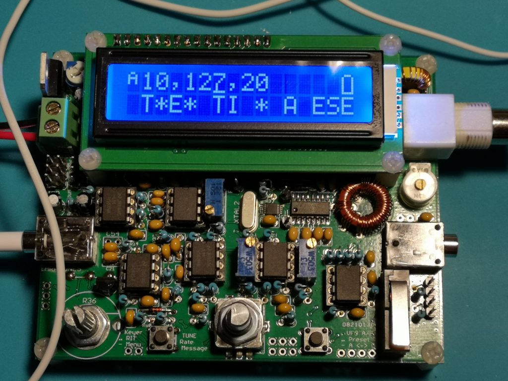
Calibration is easy, follow the instructions to optimise the rx and tx.

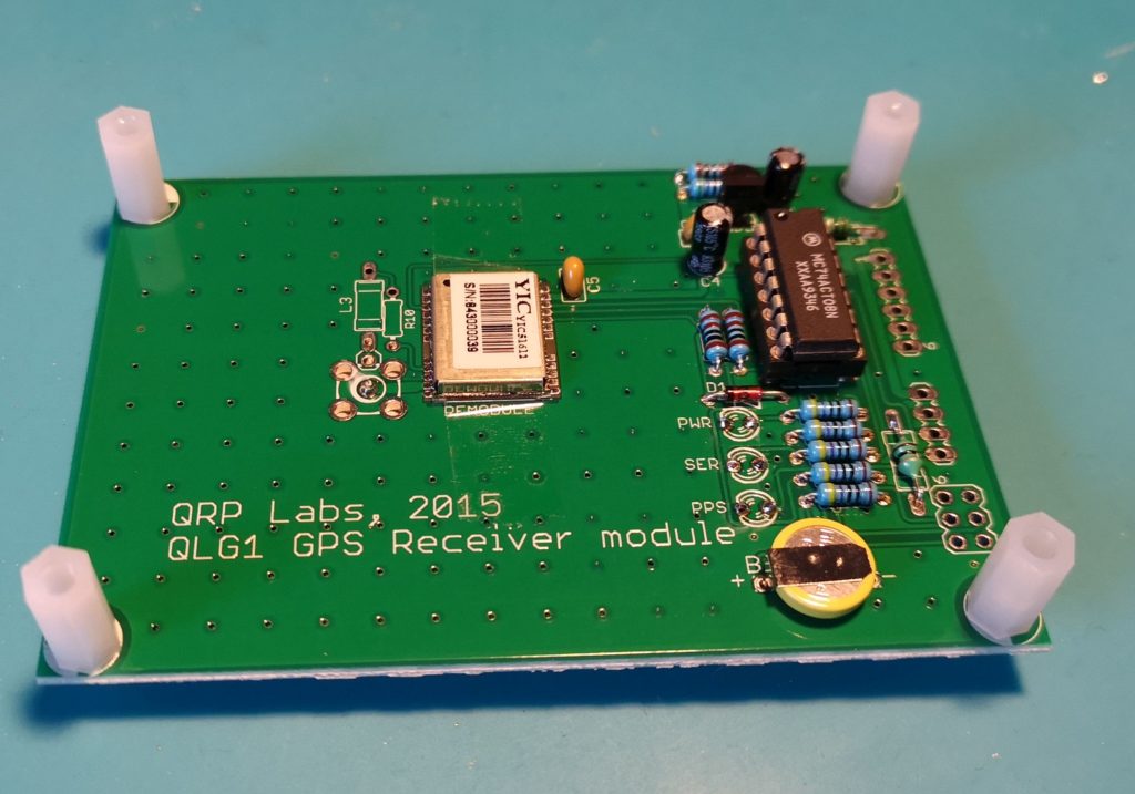
If you have the Qrp Labs GPS unit, make a 4 way lead to connect the GPS to the QRX PCB. This is not clear in the instructions.

The GPS is powered from the 4 way connector on the QCX pcb – no external power needed for the GPS – make sure your pin to pin connections are correct by referring to the manuals and schematics for both units.

By selecting the correct menu function, the GPS will set the frequency offsets etc in less than 30 seconds and you are ready for the tx optimisation.

PCB in the custom case

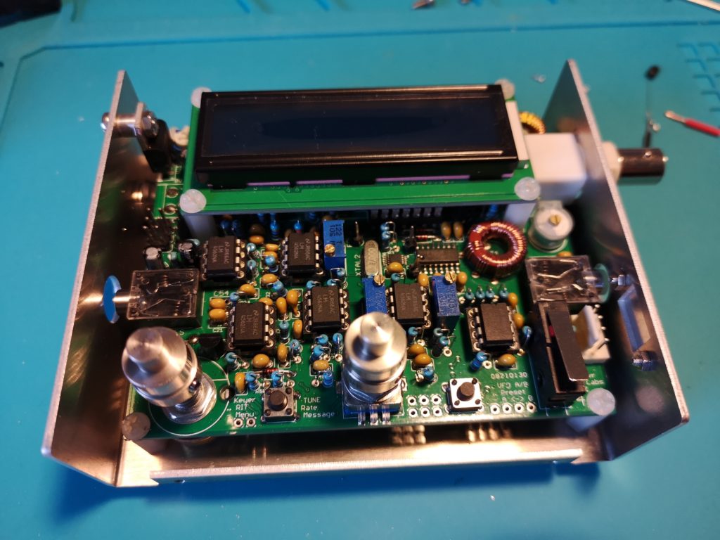
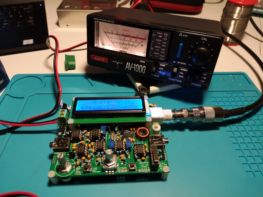
Hans produced a comprehensive video showing the procedure for optimising the BPF and how to increase the TX power.

Video here

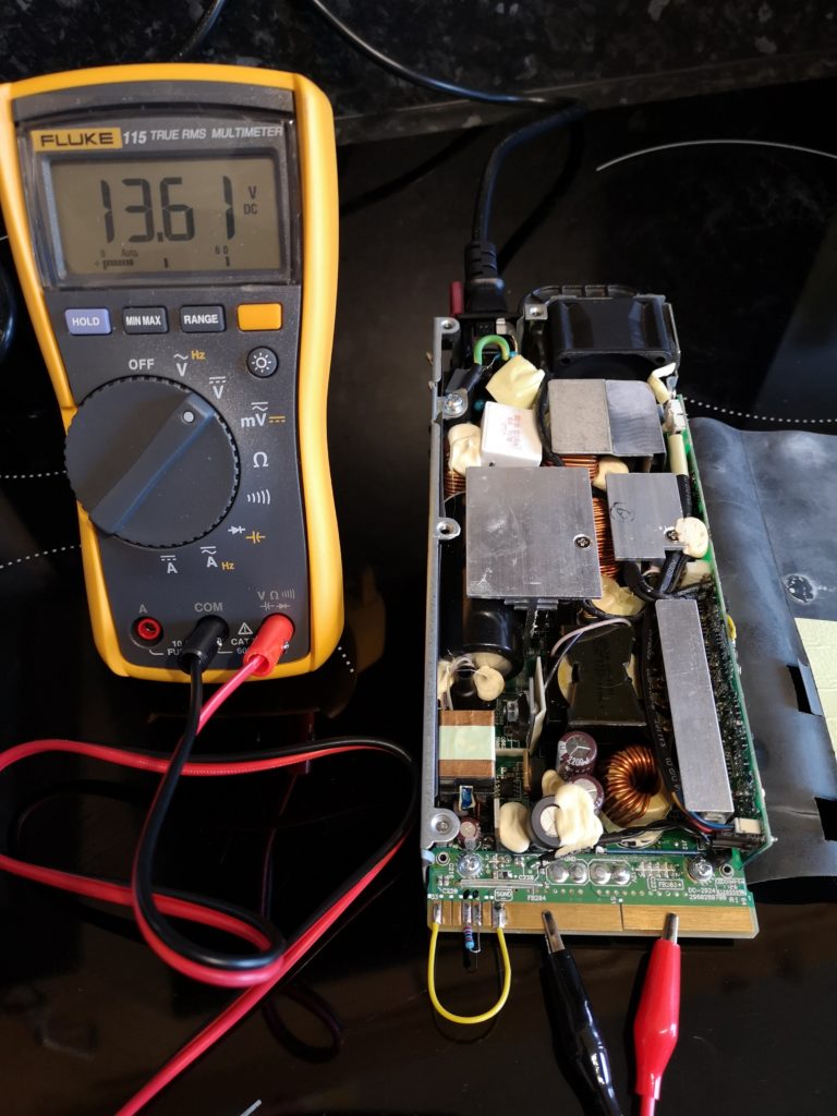
Following the guidance on the video, 2 turns were taken off the torroid and the others either pinched or expanded as described. Power output increased from 0.7w to 3.8w at 12v.

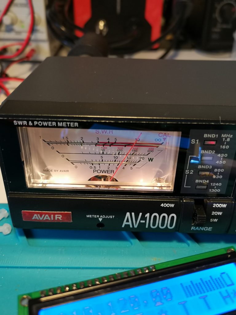
At 13v the power was just over 5w.

Text book tuning!

The last thing on the list is to source a 5.5mm/2.1mm power connector to marry up with the Bamotech supplied power socket – frustrating that they dont supply the power plug with the case kit.

RS components in the UK have the plugs, but with £4.95 postage on an 88p plug, it is a bit steep.

3.5w at 12v

Very happy with this radio, a lot of thought has gone into the design and the user manuals, and using a home built radio is very satisfying.

73

Tim

50A Power supply for peanuts

Following the successful repair of the MML144-200 2m Amp, and needing a high current stabilised power supply to feed it, I cannot thank Len, GM0ONX enough for putting me on to this server power supply.

Designed to run 24/7/365 for 7 years without maintenance, and provide up to 63A continuous current output at 12v, you would think that you couldn’t afford one – especially as it says HP on the rating plate.

Think again.

These power supplies are switch mode units, and as such are generally avoided like the plague for radio use. However, this model for me at least is RF quiet on the bands I operate.

The best part is I purchased two guaranteed working used units from eBay (12th Feb 2021) for £15 delivered – that was for both of them! £7.50 each. Significantly cheaper than a new desktop PSU from one of the radio suppliers.

HP server PSU

Very important: – Make sure the model number is this:

HP ProLiant DL360 G6 750W Power Supply (HSTNS-PD18 version)

Google or Youtube will provide loads of information on modifying server power units.

This post only applies to the model shown above.

There are a couple of very simple mods to do to them before you can use them.

  1. Power on mod
  2. Variable voltage mod

As these are designed to be installed in a server you will need to bypass the server start up and monitoring system.

On the edge connector solder a jumper between the first pin and the ground tab (shown by the yellow wire)- you can also add a switch if you want to, or as soon as power is applied the device will turn on.

Next add a 22k resistor as shown below (between pins 4th from the left and 5th from the left)

Jumper first pin to Ground (-Ve) and a 22k resistor between 4 + 5 as shown

Connecting power will start the power supply, you should see 12v on the edge connector (polarity as shown with the black and red croc clip)

The next job is to mod the regulator to allow adjustment to 13+ Volts.

Add a 22k resistor between the left leg of the potentiometer, and the fourth pin from the right on the vertical board as shown below.

22k Resistor, heatshrink protected from 4th pin to left leg of pot

Connect the power and adjust the pot to the desired output, in my case 13.6v.

On my examples, at 13.8v the protection circuits can kick in and shut things down on switch on. When backed off to 13.6v the system was happy.

Place the insulating shield back into position, screw down the covers and you are good to go.

Both units worked first time, I now have a capacity of 100A plus if needed for less than £20.

A case, meters, fuse holders, and power pole chassis sockets are on order ready to box up the units, more on this shortly.

73

Tim

Microwave modules MML-144-200

This was one of those impulse purchases, you know the ones, you lusted after something when you were first licensed (15 years old in my case), but couldn’t quite justify the expense? Well due to sad circumstances one of these extremely rare blasts from the past appeared on the club web site, one of our club members had sent his last transmission and was now SK. Long story short, sealed bid auction, I won it and became the proud owner of this heavy and rather nice looking 80’s 2m amp.

There are many 30w and 100w versions in circulation, but the 200w amp is a rare beast indeed. Anyway, after hooking it up to the shack psu and turning it on, all the lights went out, not just the amp, the entire house!

Not a well amp.

Information on this version – V1 as far as I can find out, is scarce, it is a 25w input, 200w out solid state PA for 2m, current draw is going to be 40A plus I would guess. Internet searches turned up a circuit diagram of sorts and provided a place to start.

This image has an empty alt attribute; its file name is IMG_20201127_150932-768x1024.jpg
Feet in the air and bottom cover off – Sick MML200

Starting at the power leads (which were in pretty poor condition), the multi meter confirmed dead short across the leads. The circuit diagram was showing an idiot diode across the input, and as the PCB is old school, it took no finding. The multi meter again confirmed that the reverse polarity diode appeared to be short circuit. To be sure, one leg was lifted, and the diode checked again, both polarities. It was toast, short in both directions.

This image has an empty alt attribute; its file name is IMG_20210202_153437-768x1024.jpg
Reverse polarity diode – one leg lifted for checking

Luckily the junk box had a spare 1N4007, the offending article was replaced, and an ohm meter test now displayed several Meg-ohms across the input.

Power was applied again, and with the current throttle set to 3A the beast was switched on. The relays fired and the amp burst into life. Setting the mode to FM, connecting a dummy load and power meter, and giving the input a squirt of RF from an FT70, the meter deflected over to 10w, an expected output for 1w input. Increasing the drive to 5w gave 50w. The FT70 was swapped for a wouxun 2m giving 7w out, the amp gave a solid 70w.

This image has an empty alt attribute; its file name is IMG_20210205_144606-1024x768.jpg
70w out for 7w in

The power supply was starting to complain at this level due to current draw, but in all, I am feeling pretty confident that the amp will get close to the 200w with enough drive and current availability. Next tests will be spectral purity with the spectrum analyser, and then on the air to see what it is capable of once the big psu (60A) is retrieved from storage.

In summing up, I always wanted one of these back in the mid 80s, and for the price paid for it from the SK sale, very pleased that the repair cost less than 12p and 30 minutes to sort out.

Beam North and see if you can hear me on 2m SSB

73

Tim

G4YTD

QRP Labs QCX 30m kit

Whist the current lack of travel is frustrating, and the enforced “house arrest” isn’t helping much, it has given the opportunity to make progress on some of those projects that have been gathering dust for a while.

Some time ago a QCX 30m kit arrived in the post from Hans Summers of QRP labs. The kit is well packaged and contains everything you need to get on the air. I must congratulate Hans on the quality of the build notes, all 150 pages of them. This is not as daunting as it sounds, as experienced builders can skip a lot of the information, and new builders can take in the many tips and step by step instructions.

The radio is a single band 5w QRP CW only radio that has a whole host of features built in including CW keyer, CW decoder, test equipment, LCD display and ability to link to a GPS time source for WSPR transmissions and frequency calibration.

It took me a couple of nights to build, and the excellent instructions saved any problems when winding the torroids.

This image has an empty alt attribute; its file name is IMG_20210127_160026-768x1024.jpg
QCX PCB Completed

Once built, and checked for short circuits, power was applied, so far so good, no smoke! The next job is to set up the LCD, turning the brightness pot up a little illuminated the display with a prompt asking the builder to choose the band – in my case 30m (Band choice is chosen by the BPF that you build and fit to the PCB). The next step is to set up the receiver, again step by step using the built in test equipment and covered in great detail in the build notes.

This image has an empty alt attribute; its file name is IMG_20210127_170014-1024x768.jpg

At last it was time to test the TX, with a watt meter and dummy load attached, the transmitter can be tested by pressing the in built microswitch (that also acts as a straight key) the power meter kicked over to 0.8w output, not bad for a first transmission, at least there was no smoke. Using the inbuilt “key” for a quick CQ G4YTD instantly decoded on the screen. This feature can be turned off, but is a good aid for new CW operators.

This image has an empty alt attribute; its file name is IMG_20210127_172345-1024x768.jpg
First TX

Frequency offset against display was a little off when measured on a frequency counter. Hans has this covered by use of a GPS driven signal source. The QCX can take data from several GPS units, but QRP labs also offer a low cost kit to build one. I purchased one with the QCX, the build took around 1 hour to complete. At the time of writing I am waiting for a 4 way molex connector to arrive in the mail, and will then use the GPS to calibrate the QCX further.

This image has an empty alt attribute; its file name is GPS-1024x717.jpg
QRP abs GPS card

The satisfaction of listening to 30m on a home built radio took me back to when I was first licensed in 1984 using a home brew HF rig, who needs the latest gazillion £ Yaewoodcom radio to have fun?

Next steps on this project are to tweak the torroids to up the power a bit closer to 5w, and finish calibrating before boxing up in the Bamotech enclosure and giving it an airing.

73

Tim

G4YTD

Powered by WordPress & Theme by Anders Norén